Our range of measurement chambers

The magic word in EMC- and radio measurements is “reproducibility”. The trick to establishing reproducibility is to eliminate variables as much as possible. Using a stable measurement environment most of the surrounding variables are being locked out.

During an immunity test, the test itself is not allowed to influence its surrounding environment. Here as well a stable measurement environment plays part in the prevention of unwanted interactions.

We offer a range of solutions in order to create a stable test- and measurement environment.

Strip Line

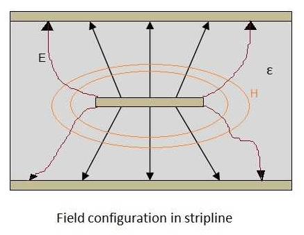
The strip line is being used for (automotive) immunity testing. Our strip line is mounted on a mobile cabinet from which the countertop can be angled. This makes the strip line mobile and easy to store. The 50 [Ω] version is detachable in two sections. Our strip line can be supplied in 50 [Ω] and 90 [Ω] impedance versions and is the only one of its kind that is usable up to 1 [GHz].

TEM-Cell

The “transversal electro-magnetic mode cell” (TEM-cell) offers a user friendly, compact and cost efficient measurement environment in order to perform EMC, EMI, pre-compliance and type approval tests and measurements and sensor calibration.

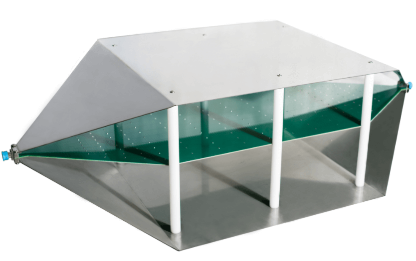
Our compact open TEM-cells are easily placed within a laboratory. Within the TEM-cell a homogeneous electric field is created with high precision up 3 [GHz]. Outside the TEM-cell the field decreases rapidly with approximately 33 [dB] per meter.

Our closed TEM-cells are commonly used to perform testing on automotive equipment. Within these cells an accurate homogeneous electric field (up to 3 [GHz]) can be produced using only little RF power. The total set-up will be much less expensive in comparison to an anechoic chamber with antennae. The electric field is polarized vertically, the magnetic field horizontally where the wave encounters an impedance of 337 [Ω]. The condition inside the cell equals those of a “far field” measurement.

GTEM-Cell

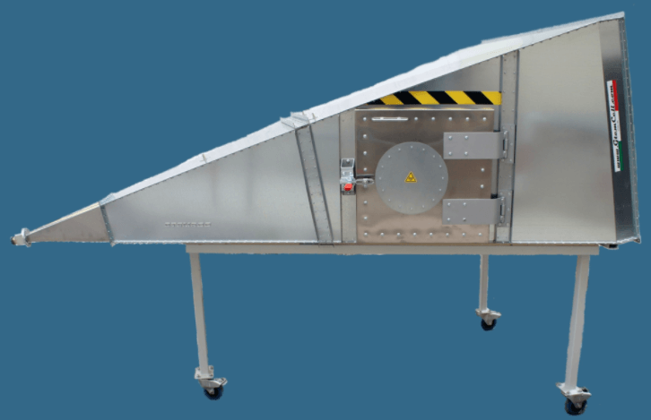
A “GTEM-cell” is the acronym for “Gigahertz Transverse Electro-Magnetic cell”. The principle of a GTEM-cell is a 50 [Ω] waveguide which diverges into a pyramid shape. In contrast to a TEM-cell no cut-off frequency is known. At the end the waveguide has a 50 [Ω] termination produced out of a combination of termination resistors and absorbing foam. This offers an excellent VSWR over the entire frequency range.

Our GTEM-cells are both a stable shielded immunity test booth as well as a stable shielded emissions measurement chamber up to 18 [GHz]. The accurate homogeneity provides reproducible measurements and tests:

  • Compliant with the basic standard IEC/EN 61000-4-20
  • Examples emission standards CISPR 14-1, IEC 61000-6-3 and IEC 61000-6-4 for wireless EUT’s
  • Example immunity standard EN 60118-13
Faraday chamber

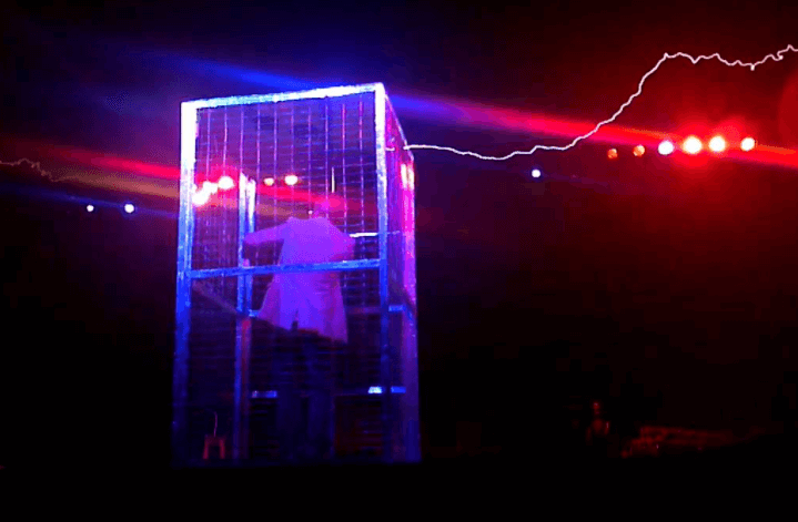
A Faraday cage is a shielding chamber with electrically conductive walls, floor and ceiling. The outside of the chamber will reflect radio waves. On the inside of the chamber the sum of the electric field distribution will cancel itself out at the perimeters, leaving no residues on the outside of the chamber. Therefore no radio waves can be transported inwards or outwards the chamber.

The construction of the metal chamber is relatively uncomplicated. Nevertheless, the construction of a radio wave impenetrable door, window, ventilation panel, power- and signal feedthroughs are for specialists.

Our product program includes:

  • Faraday cages
  • Mobile Faraday cages
  • Shielding doors and access panels
  • Shielding windows
  • Shielding ventilation panels
  • Special measurement chamber feedthrough filters for standard power, high power and signal lines
Anechoic chamber

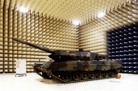
In order to determine the radio signals emitted by a device under test, a fully anechoic chamber is required. Within an anechoic chamber all radio waves are being absorbed at the walls. This simulates a device being in outer space. The outer space is infinitely large and in principle a radio wave will continue traveling indefinitely and will never return.

The base of an anechoic chamber is a Faraday cage lined on the inside with ferrite tiles to absorb radio waves under 1 [GHz] and pyramid absorbers to absorb radio waves of higher frequencies.

Our anechoic chambers can be supplied in any desired size or geometry and are fully compliant to CISPR 16-1-4, CISPR 16-2-3, CISPR 22 and IEC/EN 61000-4-3. Considering all options, please feel free to contact us about:

  • Absorber types
  • Access doors and access panels
  • Flooring
  • Illumination
  • (Forced) ventilation
  • Turn tables
  • Antenna masts
  • Camera systems
  • Cable feedthrough
  • Feedthrough filters
  • Test tables
Semi-anechoic chamber

A “semi-anechoic chamber” is the functional successor of an “open area test site” (OATS). The difference with a fully anechoic chamber is the flooring. Within a semi-anechoic chamber absorber material is attached to the walls and ceiling. The floor is conductive and reflects radio waves. Theoretically a measurement antenna can pick up a signal from both a direct path and the path that was reflected on the floor due to which the measured signal level doubles (+3 [dB]). This situation is nearer to a real life situation in the field.

Our semi-anechoic chambers can be supplied in any desired size or geometry and are fully compliant to CISPR 16-1-4, CISPR 16-2-3, CISPR 22 class B, EN 55022 and IEC/EN 61000-4-3. Please, feel free to contact us about the possibilities concerning for example:

  • Absorber types
  • Access doors and access panels
  • Flooring
  • Illumination
  • (Forced) ventilation
  • Turn tables
  • Antenna masts
  • Camera systems
  • Cable feedthrough
  • Feedthrough filters
  • Test tables
Compact automotive component testing chamber

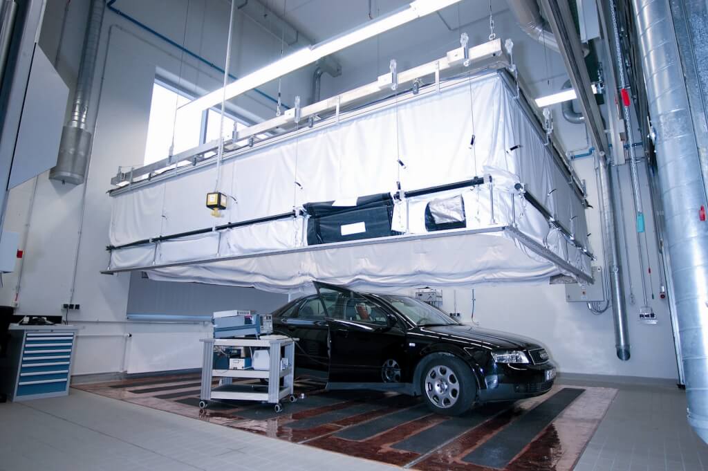
Automotive components have their own particular set of legislations. Due to their compact size it is worthwhile to use for these components a special compact anechoic chamber. Our compact hybrid anechoic chambers are fully compliant to IEC/EN 61000-4-3 for measurement distances of 1 and 3 meters, DIN/ISO 11452-2 and EN 55025 (CISPR 25).